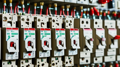
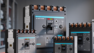
In 2026, choosing a molded case circuit breaker means balancing protection, reliability, and the demands of a changing electrical system. The International Energy Agency’s Electricity 2024 report projects global electricity demand will grow by an average of 3.4% annually through 2026. That growth makes sound protection choices increasingly important in commercial buildings, factories, and infrastructure. But higher demand alone does not determine the right breaker.
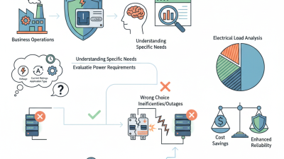
Start with the actual circuit. Check its voltage, continuous current, available fault current, and the conductor’s ampacity. Then assess trip characteristics, ambient temperature, pole configuration, and coordination with upstream and downstream devices. A breaker that fits the panel may still be wrong for the fault level. Small details matter. A warm enclosure or a motor’s starting current can change the decision.
Electrical educator Mike Holt’s safety guidance can be paraphrased as: “Match overcurrent protection to the conductor it protects.” This is a summary, not a verbatim quotation. For a defensible selection, compare manufacturer data with IEC 60947-2 or the applicable product standard, and confirm the installation design with a qualified professional. One point deserves a second look: ratings on a product label do not replace an assessment of real operating conditions. This guide explains how to compare molded case circuit breaker specifications, spot common selection errors, and choose with evidence rather than guesswork.
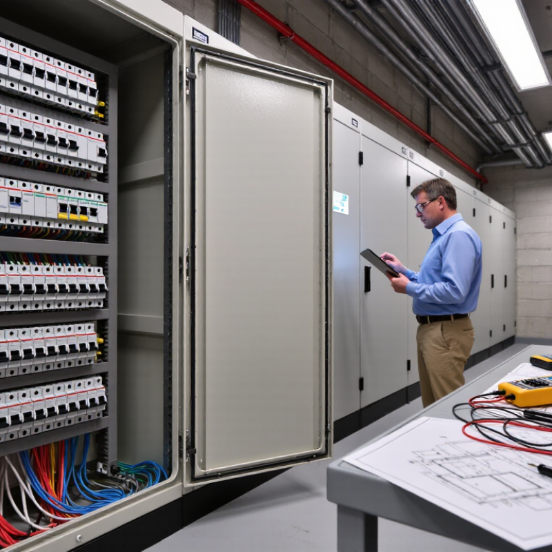
A molded case circuit breaker (MCCB) is more than an on-off switch. It protects a circuit by interrupting current when an overload or short circuit exceeds its settings. In a workshop, that may mean stopping a fault before overheated conductors damage insulation. It also gives technicians a clear way to isolate equipment for inspection. It is not a fire-prevention guarantee.
The risk is real. The National Fire Protection Association’s Home Electrical Fires report found that U.S. fire departments responded to an average of 46,700 home fires involving electrical failure or malfunction each year from 2015 to 2019. An MCCB cannot eliminate every cause, but correct protection can limit certain electrical faults. That distinction matters.
For a 2026 selection, match the breaker’s rated current and voltage to the system, then check its interrupting capacity against the available fault current. Review trip settings, conductor size, enclosure conditions, and coordination with upstream and downstream devices. A breaker that fits the panel may still be poorly matched to the circuit. That detail is easy to miss. An electrician or qualified engineer can verify the design against site conditions and applicable standards.
Start with the electrical system, not the breaker’s frame size. Record the supply voltage, phase, frequency, and the panel’s available fault current. The breaker’s interrupting rating must meet or exceed the fault current at its installation point. A rating copied from an older panel schedule may no longer be reliable after equipment changes. Small details matter.
Next, estimate the actual load and check conductor ampacity, operating temperature, and enclosure conditions. Motors, transformers, and other equipment can draw brief starting currents, so a trip setting that looks adequate on paper may cause nuisance trips in service. Compare the breaker’s trip characteristics with the load profile and the protection required for downstream conductors and equipment. Coordination matters, too: an upstream device should not trip unnecessarily for a fault that a downstream breaker can clear. That is not enough.
Check the manufacturer’s technical documentation for permitted settings, mounting limits, and terminal requirements. Confirm the selected breaker suits the system’s voltage and intended application; never assume similar-looking units are interchangeable. If the fault-current value or load data is uncertain, have a qualified electrical professional verify it using site measurements and current system records. Field conditions are imperfect, and a neat spreadsheet can still miss a warm, crowded enclosure.
Start with the system voltage and phase, not the breaker’s frame size. IEC 60947-2:2024 covers circuit breakers for systems up to 1,000 V AC or 1,500 V DC. That scope is not a substitute for checking the device’s own ratings. For example, a 480 V panel needs a breaker rated for that system voltage and configuration. Confirm the rating against the equipment label and the manufacturer’s tested data.
Next, match rated current to the conductor, load, enclosure temperature, and expected duty. A 100 A breaker is not automatically suitable for a 100 A load. Check continuous-load requirements and any adjustment factors that apply. Then compare the breaker’s interrupting rating with the available fault current at its installation point. UL 489 is a key North American safety standard for molded-case circuit breakers; verify the exact listed rating, rather than relying on the frame number. A tidy calculation can still miss a site-specific fault level.
Tips: Ask a qualified electrical professional to confirm voltage, current, and fault-current data before selection. Record the panel’s available fault current and the breaker’s interrupting rating together. Small details matter—especially after equipment changes.
Choosing a molded case circuit breaker in 2026 means matching its trip functions to the actual load and fault risks. Thermal-magnetic protection suits many standard circuits, while electronic trip units can offer adjustable settings and clearer fault information. Check the available short-circuit current and the breaker’s interrupting rating; neither should be guessed from the load’s normal current. Select the number of poles to match the system and switching needs. Neutral switching depends on the installation, so verify the design rather than assuming.
Tips: Confirm voltage, current, and fault levels against the equipment data. A quick panel label check can prevent a costly mismatch.
Optional features should solve a real operating need. Auxiliary contacts can report breaker status, while shunt trips or undervoltage releases support remote or interlocked shutdowns. Communication features may help monitoring, but they also add setup and maintenance work. It is tempting to specify every option; that can make troubleshooting harder. Review coordination with upstream and downstream protection, and have a qualified professional verify settings for the installation. A neat specification is useful, but field conditions can still surprise you.
How to read this chart: Two poles are typical for single-phase line-to-neutral circuits; three poles for three-phase circuits where the neutral is not switched; and four poles where a three-phase, four-wire circuit requires neutral switching. Confirm the arrangement against the system design and applicable electrical codes.
Choose trip functions to suit the protection study: thermal-magnetic units provide overload and short-circuit protection, while electronic trip units may add adjustable settings and functions such as ground-fault protection. Optional features can include auxiliary contacts, shunt trips, and undervoltage releases; check device ratings and compatibility before selection.
A molded case circuit breaker should match the standard required for its market and application.
Check the device markings and documentation against the applicable standard, such as IEC 60947-2 or UL 489. These standards are not interchangeable.
Confirm the breaker’s rated current and interrupting capacity against the system voltage and the prospective fault current at its installation point. A rating that looks sufficient on a panel schedule may not be sufficient at the actual bus.
Coordination matters too.
Compare the breaker’s time-current curve with those of upstream and downstream devices. Check for selective operation where continuity is important, and review the manufacturer’s tested coordination data rather than relying on curve estimates alone.
Coordination can be tricky.
Installation conditions can change the selection: ambient heat, enclosure ventilation, altitude, conductor size, and terminal torque all affect performance. Check the required clearances and mounting orientation in the instructions.
A warm, tightly packed cabinet is not the same as an open test bench.
I would also verify site conditions before finalizing a choice; drawings can be outdated, and that is easy to overlook.
Have a qualified professional confirm the design and installation against local requirements.