Choosing a surge protective device is not a box-checking exercise. It is a practical decision about voltage, wiring, equipment value, and real-world risk. A device may look impressive on a specification sheet, yet perform poorly when installation details are ignored.
Ronald B. Standler, an engineer and author of technical work on overvoltage protection, offers a useful principle: “Protection depends on the complete circuit, not the device alone.” That idea deserves attention. A surge protective device needs suitable voltage ratings, discharge-current capacity, response characteristics, grounding, and coordination with upstream protection. The shortest cable path may matter as much as the advertised performance.
Small details become important. Imagine a control panel beside a factory entrance, with a long grounding conductor looping behind it. During a transient event, that extra length can increase voltage across sensitive components. The label alone cannot reveal this weakness.
This guide presents 10 practical tips for selecting a surge protective device. It considers service voltage, system configuration, installation location, modes of protection, and maintenance needs. It also examines standards, indicator functions, and replacement planning.
There is no perfect choice.
Even experienced engineers can underestimate changing site conditions, especially after electrical renovations or equipment expansion. A careful selection process therefore combines manufacturer data, field inspection, and qualified professional judgment. The goal is not simply to buy the strongest device. It is to choose protection that matches the system, the threat, and the equipment that cannot afford an unexpected shutdown.
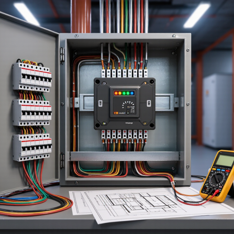
Tip 1: Map the installation before choosing an SPD. IEC 61643-11 separates Type 1, Type 2, and Type 3 by test duty and location. Type 1 belongs near the service entrance, where lightning current may enter. It uses the 10/350 μs impulse.
Tip 2: Confirm whether the building has an external lightning protection system.
Tip 3: Check the earthing arrangement and available fault current. A strong device can still perform poorly with long, inductive conductors.
Tip 4: Use Type 2 at distribution boards. It is tested with the 8/20 μs current wave and manages induced or switching surges.
Tip 5: Place Type 3 close to sensitive loads, such as control panels or medical electronics.
Tip 6: Coordinate upstream and downstream protection. CIGRE Technical Brochure 549 notes that lightning current characteristics vary widely, so one rating cannot describe every event.
Tip 7: Compare Uc, Up, In, and Imax, not only the product label. Measure twice.
Tip 8: Keep connecting leads short and straight.
Tip 9: Review maintenance access, remote indication, and replacement requirements. NOAA’s National Severe Storms Laboratory estimates roughly 25 million lightning flashes occur annually in the United States. That exposure makes installation discipline practical, not theoretical.
Tip 10: Verify the design against IEC 61643-11 and applicable local codes.
I have seen specifications choose Type 2 everywhere, which seems simple but ignores the service entrance. The uncomfortable lesson is clear: protection type follows installation position, not marketing language.
Choosing a surge protective device starts with matching its Uc or MCOV rating to the system’s nominal voltage. Uc, also called MCOV, is the highest continuous voltage the device can withstand without conducting repeatedly. It should not sit below the system’s normal operating voltage. Otherwise, the protector may heat up, age quickly, or disconnect during ordinary voltage fluctuations.
Tip: Check the actual system voltage, not only the label. A “230 V” circuit may operate above that value, especially where voltage tolerance, long cable runs, or generator supply is involved. Confirm whether the system is single-phase, three-phase, grounded, or ungrounded. Then compare each protected conductor’s voltage with the manufacturer’s Uc specification. Small details matter here.
A higher Uc rating is not automatically better. It may reduce protection sensitivity and allow a higher residual voltage during a surge. A lower rating may respond earlier, but it can suffer from temporary overvoltage. I have seen selections based only on nominal voltage, and they looked reasonable until switching events caused repeated failures. That mistake is easy to make. Check the power-quality history, temporary overvoltage conditions, and installation category before choosing. When the values remain uncertain, measure the circuit and ask a qualified electrical engineer to review the decision.
| System Nominal Voltage | Typical Voltage Reference | Common Uc/MCOV Range | Recommended Matching Approach | Reason for Selection | Important Check |
|---|---|---|---|---|---|
| 120 V AC, single-phase | 120 V line-to-neutral | 150–175 V AC | Choose Uc/MCOV above the highest normal operating voltage, commonly around 150 V AC or higher. | Provides operating-voltage margin while allowing the SPD to respond to transient overvoltage. | Verify the actual service voltage, neutral arrangement, and temporary overvoltage exposure. |
| 120/208 V AC, three-phase | 120 V line-to-neutral; 208 V line-to-line | 150 V AC for line-to-neutral protection; device-specific values for line-to-line protection | Match each protection mode to the voltage that appears across its connected terminals. | Different SPD modes can experience different steady-state voltages in a 120/208 V system. | Check the wiring diagram and the Uc/MCOV rating for every mode: L-N, L-L, and N-PE. |
| 230 V AC, single-phase | 230 V line-to-neutral | 275 V AC | A 275 V AC Uc/MCOV rating is commonly used where the system and installation conditions are suitable. | 275 V provides a practical margin above a 230 V nominal supply. | Confirm the permitted voltage tolerance and temporary overvoltage conditions before final selection. |
| 230/400 V AC, three-phase, four-wire | 230 V line-to-neutral; 400 V line-to-line | 275 V AC for line-to-neutral protection | Use an SPD configuration specifically rated for 230/400 V systems and select Uc/MCOV according to each connection mode. | The line-to-neutral voltage normally determines the Uc/MCOV requirement for L-N modes. | Ensure the SPD has the correct pole arrangement and an appropriate neutral-to-earth protection path. |
| 277/480 V AC, three-phase | 277 V line-to-neutral; 480 V line-to-line | Typically 320 V AC or higher for line-to-neutral modes, subject to the system design | Select an SPD rated specifically for 277/480 V service; do not substitute a 230/400 V unit. | A higher nominal system voltage requires a correspondingly higher continuous operating-voltage rating. | Review the manufacturer-independent technical specification for maximum system voltage, connection mode, and fault current capability. |
| 400/690 V AC, three-phase | 400 V line-to-neutral where applicable; 690 V line-to-line | Typically 440 V AC or higher for applicable phase-to-neutral modes | Use an SPD designed for 690 V systems and verify the exact voltage across each protected mode. | Industrial systems may have substantial voltage between phases and different earthing arrangements. | Confirm compatibility with the system earthing method, temporary overvoltage level, and required protection configuration. |
| 24 V DC control or instrumentation circuit | 24 V DC nominal | Commonly 30–36 V DC, depending on the circuit’s maximum normal voltage | Select a DC-rated SPD whose Uc/MCOV exceeds the highest continuous DC voltage, including charger or supply tolerance. | DC circuits can operate above nominal voltage during charging or regulated supply conditions. | Use only an SPD rated for DC operation and verify polarity, leakage current, and maximum continuous voltage. |
| 48 V DC telecommunications or power circuit | 48 V DC nominal | Commonly 60–75 V DC, depending on the operating and charging range | Base the Uc/MCOV choice on the highest measured or specified steady-state voltage, not only the nominal label. | Battery-backed systems may remain above 48 V during float or equalization charging. | Check the DC system’s maximum voltage, short-circuit current, grounding method, and required signal bandwidth. |
Selection note: Uc, also called MCOV in many specifications, is the maximum continuous voltage the SPD is designed to withstand without unacceptable conduction. The selected value should be at least as high as the highest continuous voltage that can occur across the SPD connection. A higher Uc/MCOV can improve immunity to sustained overvoltage but may also increase the voltage protection level, so confirm coordination with the equipment’s impulse withstand rating and the applicable installation standard.
Selecting a surge protective device starts with understanding In and Imax on the 8/20 µs waveform. This waveform represents a short, high-current surge, not a normal operating condition. In is the nominal discharge current the device can repeatedly handle during testing. Imax is its maximum discharge current rating under defined test conditions. These values describe different levels of stress.
Tip: Match In to the site’s expected surge exposure, not only the largest number on a datasheet. A device near a service entrance may face stronger events than one inside a protected panel. Consider lightning activity, overhead lines, grounding quality, and the building’s location. Field assessments often reveal that installation conditions matter as much as the rating.
A higher Imax does not automatically mean better protection. It may indicate greater surge endurance, but clamping voltage, response behavior, wiring length, and coordination still affect performance. Keep connections short and direct. Long conductors add inductive voltage during the surge. That detail is easy to miss.
Tip: Compare In and Imax using the same 8/20 µs test basis. Do not compare ratings from different waveforms without checking the test standard. Also verify the device’s short-circuit protection and follow-up current behavior. A careful specification should reflect the actual electrical system, not an attractive headline value. The selection process is rarely perfect. Recheck assumptions before approval.
Choosing a surge protective device requires more than checking its maximum discharge current. Protection performance starts with Up, the measured voltage across the device during a surge. A lower Up generally means less stress reaches connected equipment. However, the value only matters when tested under a comparable setup.
IEC 61643-11 specifies a 1.2/50 µs voltage impulse for insulation stress testing. It also uses the 8/20 µs current impulse to represent surge current behavior. These figures are not decorative. They define the waveform, test energy, and response conditions. IEEE C62.41.1 and IEEE C62.41.2 further classify surge environments by installation location and exposure level.
Check the test report carefully. Confirm the stated Up, test current, voltage, and connection mode. A device rated at 1.5 kV under one configuration may show a different result elsewhere. That is easy to miss. I have seen specifications compare Up values without matching the test impulse, which can create a false impression of performance. For sensitive control systems, compare Up with the equipment’s impulse withstand rating, not only its operating voltage. Leave practical margin for wiring inductance, because long conductors can add voltage during a fast event. Real installations are rarely as clean as laboratory diagrams.
The normalized 1.2/50 µs voltage impulse reaches its peak at approximately 1.2 µs and decreases to 50% of peak voltage at approximately 50 µs. When selecting an SPD, compare its declared Up value with the equipment's rated impulse withstand voltage. A lower Up generally provides a greater protection margin, provided the SPD is correctly coordinated with the system.
Choosing a surge protective device requires more than checking its voltage rating. Verify that the device complies with UL 1449 or IEC 61643-11, according to the project’s required market and installation standard. These standards address performance, safety, testing, and failure behavior. Confirm the edition and certification details. Standards change.
Check the maximum continuous operating voltage against the system voltage and grounding arrangement. A mismatch can cause nuisance operation or premature failure. Review the device’s surge current rating, protection level, and short-circuit rating. These figures should match the equipment and expected fault conditions. I also examine the installation record, conductor length, torque settings, and enclosure space. Small details matter.
Backup fusing needs careful coordination. Use the specified fuse or circuit breaker rating, not an approximate replacement. Confirm its interrupting capacity and compatibility with the protective device. The backup device must clear a failed SPD without creating an unsafe condition. It should also preserve normal surge protection during routine events. A field mistake I have seen is selecting a large upstream fuse for convenience. That can leave the SPD poorly protected. Coordination tables are useful, but they are not always enough; actual system fault levels and wiring conditions deserve a second review. Shorter leads help. Fresh inspection helps more.