Choosing a switch disconnector is a practical decision about safe control, clear isolation, and dependable equipment operation. In a workshop panel, for example, an operator may need to disconnect a motor circuit before inspection. The device should suit that task, not merely fit the available space.
A switch disconnector can combine load switching with an isolating function, when selected and installed for the intended application. Its rated operational current, voltage, utilization category, and pole configuration should match the circuit. Check the manufacturer’s data, too. A switch disconnector is not automatically a substitute for overcurrent protection, and its short-circuit withstand capability must be considered alongside upstream protective devices. Small details matter: enclosure rating, terminal access, operating handle position, and the space needed for safe maintenance.
The right choice depends on the system and the people who use it. A compact unit may suit a confined machine panel, while a larger, lockable handle can make isolation clearer on a busy production floor. Clear labeling helps. So does a realistic review of how often the device will operate and who will maintain it. There is no universal best model. Selection should follow the equipment’s requirements and the manufacturer’s instructions, with qualified personnel confirming the design. Even a careful specification can miss something, so installation conditions deserve a second look. That pause is worthwhile.
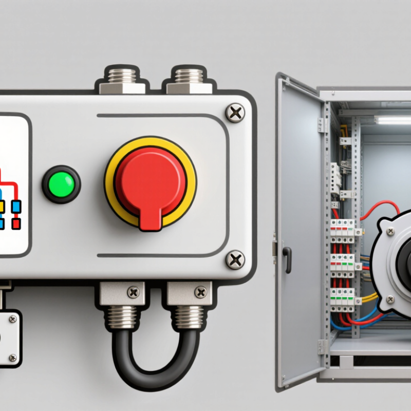
A switch disconnector is a device that can open and close an electrical circuit under specified normal operating conditions. In its designated open position, it also provides an isolation function, helping separate equipment from its power supply during inspection or maintenance. Its ratings matter: the device must suit the circuit’s voltage, current, and expected load. Not a circuit breaker. A switch disconnector generally does not automatically interrupt overload or short-circuit faults, so separate protective devices may be required.
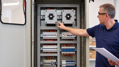
You may find one in a distribution panel, near a motor, or beside industrial equipment that needs a clear means of isolation. The handle position should be easy to identify, and the device should be accessible without reaching past live components. Before maintenance, follow the site’s isolation and verification procedures; an open handle alone should not be treated as proof that equipment is safe. This distinction is easy to underestimate, especially when panel labels are vague. A well-chosen switch disconnector makes isolation clearer, but selection still depends on the actual installation and its operating conditions.
A switch disconnector opens or closes a circuit through a manually operated handle or, on some equipment, a motorized mechanism. The linkage moves its contacts apart or together. When opening a current-carrying circuit, an arc may form between the contacts. Arc-control components help cool and extinguish it within the device’s rated switching capacity. The details matter: IEC 60947-3 sets requirements for switches, disconnectors, and switch-disconnectors, including their operating duties.
A switch disconnector can provide load switching and isolation when correctly rated. It is not normally a substitute for a circuit breaker or fuse during a short circuit; upstream protection must clear that fault. That distinction is easy to miss. In the OFF position, the device’s specified isolation arrangement separates the circuit, but workers should follow site procedures, secure the device against re-energization, and verify the absence of voltage. A handle position alone is not proof.
The NFPA report Home Electrical Fires (2022) estimates an average of 24,200 U.S. home electrical fires annually from 2015 to 2019. This figure does not measure switch-disconnector performance, but it shows why safe isolation deserves careful attention. Selection should match the circuit’s voltage, current, load type, and expected switching frequency. Sizing by current alone can be a mistake.
A switch disconnector combines circuit switching with a means of isolation, helping technicians separate equipment from its supply during inspection or maintenance. Its clear operating position and, on suitable models, lockable handle can reduce the chance of accidental re-energization. That matters beside a noisy pump or a crowded control cabinet, where a small mistake can have serious consequences. Check the device’s rated voltage, current, utilization category, and short-circuit coordination against the actual load. A switch disconnector is not automatically a substitute for overcurrent protection.
The risk is not abstract. NFPA’s Electrical Fires report, based on U.S. data from 2015–2019, estimates that electrical distribution or lighting equipment was involved in about 32,620 home structure fires annually. The report does not measure the effect of disconnectors, but it underscores why sound isolation and maintenance practices matter. IEC 60947-3 provides requirements for switches and disconnectors; selecting a device designed for the application supports dependable operation and safer servicing. Still, installation, labeling, and verified isolation procedures matter just as much.
Tip: Before work, identify every supply, switch off the correct device, secure its handle where supported, and verify absence of voltage with a suitable tester. Do not assume an open handle proves a circuit is dead. Check the manufacturer’s instructions and have a qualified person confirm the isolation method.
| Benefit | How It Works | Application Value | What to Check |
|---|---|---|---|
| Isolation for maintenance | Provides a means of disconnecting a circuit from its supply. A device suitable for isolation is designed to meet the applicable isolation requirements. | Helps create a defined point for isolating equipment before inspection or maintenance. | Confirm the device is rated and marked for isolation, and follow the site’s lockout and verification procedures. |
| Load switching | A switch-disconnector can make and break currents within its specified utilization category and ratings. | Allows operators to switch compatible circuits without using a separate switching device. | Match the utilization category, operating current, voltage, and switching duty to the actual load. |
| Clear operating status | An operating handle and position markings indicate the device’s commanded ON or OFF state. Some designs also provide visible contact position. | Can make routine operation and identification of an isolation point more straightforward. | Check the device’s indication method; an OFF indication alone does not verify that a circuit is de-energized. |
| Support for safe work practices | Compatible designs may accept a padlock or other locking accessory to help prevent unintended operation. | Can support lockout procedures while work is being carried out on isolated equipment. | Verify the available locking provision and use it as part of the required isolation and test-for-dead process. |
| Coordination with overcurrent protection | A standard switch-disconnector is not, by itself, overcurrent protection. Protection is normally provided by a suitably coordinated fuse or circuit breaker, unless the selected unit incorporates a protective function. | Combining switching and isolation with correctly selected protection helps address different circuit requirements. | Check short-circuit ratings, protective-device coordination, and the manufacturer’s installation instructions. |
| Application-specific installation | Devices are available in different pole configurations, enclosure styles, and current and voltage ratings. | Enables selection for distribution boards, machinery, and other circuits where a local switching and isolation point is needed. | Consider the supply system, number of poles, ambient conditions, enclosure protection, cable requirements, and applicable standards. |
Switch disconnectors are common in factory distribution boards, machine control panels, and commercial building services. They let technicians isolate a circuit or item of equipment during planned maintenance. On a production line, for example, a clearly marked handle near a motor can provide a practical isolation point. The device must match the circuit’s voltage, current, and switching duty; a disconnect is not automatically suitable for every load.
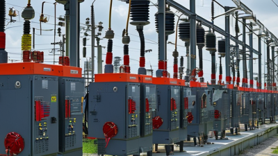
They are also used in solar photovoltaic systems, battery installations, and HVAC equipment. IRENA’s Renewable Capacity Statistics 2025 reports that global renewable power capacity grew by 585 gigawatts in 2024, with solar accounting for 452 gigawatts. That growth means more installations need correctly rated isolation points, particularly on DC circuits. The scale is real. In buildings, disconnectors may be fitted near air-conditioning units or distribution equipment, where access and enclosure protection matter. Check the details. Verify the manufacturer’s ratings, applicable installation standards, and site procedures before selecting a device. A label alone does not prove safe isolation.
Common applications and representative system-voltage examples
Switch disconnectors are commonly used in building distribution, industrial equipment, and photovoltaic systems to provide isolation for maintenance or safety. The voltage values shown are representative system examples, not device ratings; always select equipment suitable for the installation’s voltage, current, AC/DC duty, and applicable standards.
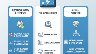
Choosing the right switch disconnector begins with the circuit’s operating conditions. Check the system voltage, rated current, number of poles, and the type of load being switched. A motor circuit, for example, can place different demands on contacts than a resistive heater. Confirm the device’s switching category matches the application, and coordinate its short-circuit rating with the upstream protective device. A switch disconnector provides switching and isolation; do not assume it replaces overcurrent protection. Small details matter.
Tips: Compare the nameplate ratings with measured or documented circuit values. Check enclosure protection, ambient temperature, mounting position, and cable space. Leave enough room for safe operation and inspection.
Think about how the device will be used every day. Will an operator need a visible isolation position? Is the handle reachable without moving nearby equipment? For a dusty workshop or damp utility room, choose an enclosure suited to the environment and follow its installation instructions. Also consider maintenance access and the consequences of an unexpected shutdown. It is easy to focus only on current rating, but that can miss practical issues. Review the circuit diagram and equipment documentation with a qualified electrical professional before final selection; the best choice depends on the complete installation, not one number on a label.