2026 Best Miniature Circuit Breaker Types for Global Buyers
Choosing the right miniature circuit breaker is not a simple catalog exercise. Global buyers must match protection performance, system voltage, installation conditions, and local requirements.
This guide examines the 2026 miniature circuit breaker types most relevant to international procurement. It compares B, C, and D tripping curves for different loads. It also considers single-pole, double-pole, neutral-switching, DC, and high-breaking-capacity designs. A domestic lighting circuit may need different protection from a motor-driven pump or solar battery system. Small details matter, including terminal size, busbar compatibility, enclosure space, and operating temperature.
Real purchasing decisions involve more than technical labels. Buyers should review test reports, product markings, factory quality controls, and documented compliance with applicable standards. IEC 60898-1 may suit certain household and similar installations, while IEC 60947-2 can apply to broader industrial equipment. Requirements vary by market, so certificates should be checked against the project location and intended use. Ask for traceable data.
There is no universal “best” type. A D-curve breaker may prevent nuisance tripping for high inrush motors, yet it can be unsuitable for ordinary lighting circuits. A compact 1P+N model saves space, but its switching arrangement deserves careful verification. Even experienced buyers can overlook ambient temperature derating or short-circuit capacity. This guide therefore treats selection as a practical risk review, not a ranking exercise. Some specifications look impressive on paper. They still need field evidence.
Understanding MCB Operating Principles, Poles, Curves, and IEC 60898-1 Ratings
2026 Best Miniature Circuit Breaker Types for Global Buyers
An MCB protects a circuit through two release mechanisms. A bimetal strip responds to sustained overloads and bends gradually. A magnetic release reacts almost instantly to short-circuit current. This difference explains why an MCB may trip after minutes or within milliseconds. Small details matter.
Pole selection depends on the circuit arrangement. A 1P device usually interrupts one live conductor, while a 1P+N model also switches the neutral. Two-pole versions disconnect both conductors in single-phase systems. Three-pole and four-pole units serve three-phase circuits, with four-pole designs switching the neutral. Neutral protection and isolation should match the installation design, not just the available space inside the panel.
Trip curves require practical judgment. Under IEC 60898-1, B curve magnetic tripping commonly occurs at 3–5 times rated current, C curve at 5–10 times, and D curve at 10–20 times. B suits lighting and resistive loads. C handles moderate starting currents from pumps or small motors. D is intended for heavy inrush, but it can leave ordinary wiring less protected if selected carelessly. A field review should check rated current, voltage, frequency, pole configuration, and Icn, the rated short-circuit capacity. IEC 60898-1 commonly covers MCBs up to 440 V, 125 A, and 25 kA, but the exact product marking still matters. Installation temperature, conductor size, terminal torque, and enclosure ventilation can change real performance. A catalogue match is not enough.
2026 Best Miniature Circuit Breaker Types for Global Buyers
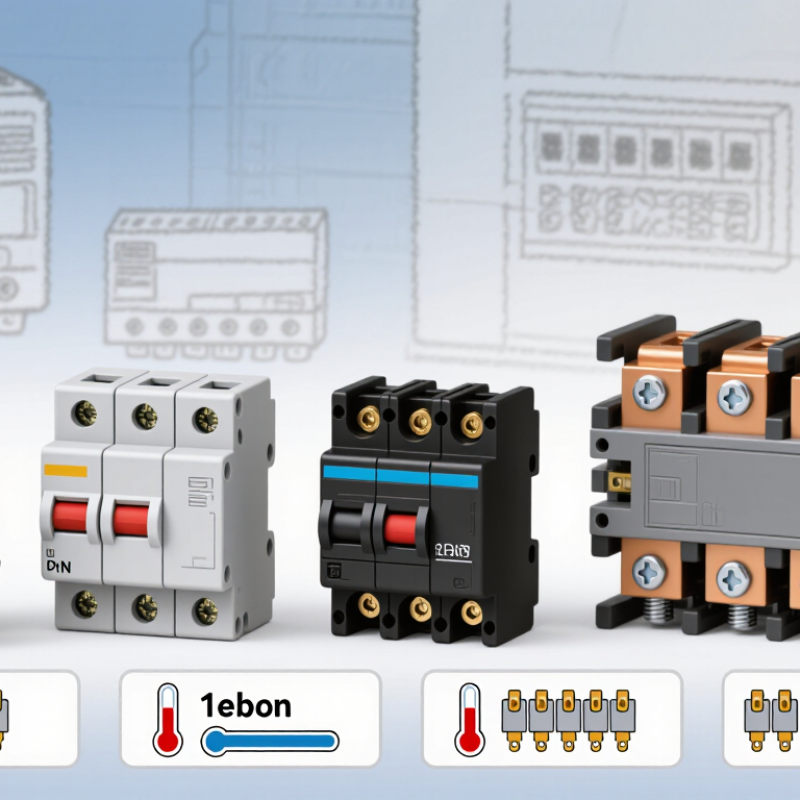
MCB operating principles, poles, curve characteristics, and IEC 60898-1 instantaneous tripping ranges
How to read the chart: Under IEC 60898-1, the magnetic instantaneous tripping range is expressed as a multiple of the rated current (In). Curve B is generally suited to low inrush loads, Curve C to common residential and commercial loads, and Curve D to equipment with high starting currents.
Pole selection: 1P protects one live conductor, 2P switches and protects two conductors, 3P is used for three-phase circuits, and 4P also switches the neutral conductor where required by the installation design. Thermal protection responds to sustained overloads, while magnetic protection responds rapidly to short-circuit currents.
Comparing B, C, and D Trip Curves: 3–5×, 5–10×, and 10–20× In
Choosing a miniature circuit breaker starts with its trip curve, not only its rated current. The curve controls how quickly the breaker responds to sudden overcurrent. A B-curve breaker trips magnetically at about 3–5× In. For a 10 A unit, that means roughly 30–50 A. It suits lighting, sockets, and circuits with limited startup surge.
A C-curve breaker responds at about 5–10× In. A 10 A C-curve device may tolerate approximately 50–100 A briefly. This makes it useful for small pumps, fans, transformers, and workshop tools. D-curve protection trips at about 10–20× In, or 100–200 A for a 10 A breaker. It is intended for equipment with strong inrush current, such as larger motors or certain industrial power supplies.
The numbers need careful interpretation. They describe the magnetic trip zone, not permission to ignore cable capacity. Field commissioning often reveals a practical issue: a D-curve breaker may prevent nuisance trips, yet fail to disconnect quickly on a high-resistance fault. That trade-off deserves measurement. Check prospective short-circuit current, conductor length, ambient temperature, and upstream coordination. A C-curve is not automatically safer than a B-curve. It may simply be a poor match for a sensitive circuit. Selection should follow the equipment’s measured startup behavior and the breaker’s verified technical data, with local installation requirements checked before purchase.
2026 Best Miniature Circuit Breaker Types for Global Buyers - Comparing B, C, and D Trip Curves: 3–5×, 5–10×, and 10–20× In
| Comparison Dimension |
Type B |
Type C |
Type D |
| Instantaneous magnetic trip range |
3–5 × In |
5–10 × In |
10–20 × In |
| Meaning of In |
In is the rated current of the circuit breaker, expressed in amperes (A). |
| Example for a 10 A breaker |
Instantaneous magnetic operation within approximately 30–50 A |
Instantaneous magnetic operation within approximately 50–100 A |
Instantaneous magnetic operation within approximately 100–200 A |
| Typical load profile |
Low inrush current and mainly resistive loads |
Moderate starting or inrush current |
High starting or inrush current |
| Common application examples |
Lighting circuits, socket outlets with limited inrush, heating elements, and general residential circuits |
Small motors, fluorescent or LED lighting groups, transformers with moderate energizing current, and commercial circuits |
Motors with substantial starting current, transformers, solenoid loads, and equipment with high magnetizing inrush |
| Resistance to nuisance tripping |
Lowest; responds more readily to short-duration inrush |
Medium; a common compromise for mixed loads |
Highest; tolerates greater short-duration inrush before magnetic operation |
| Overload protection |
Provided by the thermal tripping mechanism; the B, C, or D designation primarily identifies the instantaneous magnetic trip characteristic. |
| Short-circuit protection |
All three curves provide rapid magnetic protection when the prospective fault current reaches the applicable trip range, subject to the breaker’s rated breaking capacity. |
| Selection priority |
Use when the circuit can tolerate a lower magnetic trip threshold and the load has minimal inrush. |
Use for general-purpose circuits where moderate inrush is expected. |
Use only when the installation design confirms sufficient fault current and the connected equipment requires higher inrush tolerance. |
| Important design check |
Verify conductor ampacity, voltage, ambient temperature, installation method, prospective short-circuit current, breaking capacity, selectivity, and local electrical regulations before selection. |
| International reference |
The B, C, and D instantaneous trip bands are commonly specified under IEC 60898-1 for circuit-breakers used in household and similar installations. Confirm the applicable national or regional standard for the project. |
Buyer note: A higher curve designation does not mean greater overall protection. Choose the lowest trip curve that avoids nuisance tripping while maintaining adequate fault clearance and complying with the installation design.
Selecting 6 kA vs 10 kA Breaking Capacity Under IEC 60898-1
For global buyers, the 6 kA versus 10 kA decision starts with prospective short-circuit current. IEC 60898-1 evaluates miniature circuit breakers for household and similar installations. Its breaking-capacity rating describes the fault current the device can interrupt safely, not the circuit’s normal operating load. A 6 kA breaker may suit many apartments with modest utility fault levels. A 10 kA model offers greater interruption margin near transformers, commercial panels, or dense urban networks.
Check the source.
The International Energy Agency’s Electricity 2024 report forecasts global electricity demand to grow by about 3.4% annually through 2026. More electric heating, charging equipment, and distributed generation can increase panel complexity. However, rising demand does not automatically require 10 kA protection. Engineers should verify the utility’s declared fault level, transformer rating, conductor length, and upstream impedance. A short cable run from a powerful transformer can create a much higher fault current than a similar household circuit farther away.
Do not guess.
In practical purchasing work, 10 kA is often the cautious selection when network data is incomplete. Yet that choice can be incomplete without checking coordination, enclosure space, terminal capacity, and local installation rules. IEC 60898-1 compliance should be supported by credible test documentation, not only a printed rating. I would recheck every borderline case, especially where several protective devices share one distribution board. The larger number is not automatically the better design.
Matching AC/DC Voltage and 1P–4P Configurations Across Global Markets
Selecting a miniature circuit breaker in 2026 means matching voltage, poles, and installation practice—not simply choosing the highest current rating. IEC 60898-1 covers many household and similar AC applications, while IEC 60947-2 addresses broader industrial protection requirements.
A 1P device commonly interrupts one live conductor in a single-phase circuit. A 2P device can disconnect line and neutral together. Three-phase systems generally use 3P protection, while 4P versions add neutral switching for three-phase, four-wire installations. Local rules still matter.
AC and DC selection requires extra care. A 230/400 V AC network is not equivalent to a 250 V DC circuit. DC arcs do not naturally cross zero, so the breaker must carry an appropriate DC rating and polarity arrangement.
The IEA PVPS Trends 2024 report recorded about 407 GW of new solar capacity in 2023, pushing global cumulative capacity beyond 1.6 TW. That expansion increases demand for reliable DC protection in rooftop arrays, storage systems, and control cabinets.
In field inspections, I check the voltage marking first, then terminal polarity, conductor size, and available fault current.
A neat product table can mislead.
Regional habits complicate selection. North American panels may use 120/240 V split-phase systems, while many markets use 230/400 V networks. A 4P breaker may suit a commercial distribution board, but it can be unnecessary in a simple single-phase enclosure.
I have seen installers focus on pole count and overlook DC series-pole instructions. That mistake deserves more attention.
Manufacturers’ wiring diagrams and national requirements should confirm every final choice.
Evaluating 2026 MCBs Under IEC 60947-2, UL 489, and Local Standards
For global buyers, MCB selection in 2026 should begin with compliance, not catalog price.
IEC 60947-2 evaluates low-voltage circuit-breakers through rated voltage, current, short-circuit capacity, temperature performance, and verification tests. UL 489 uses its own construction and testing framework for molded-case circuit-breakers. These systems overlap, but they are not interchangeable.
IEA’s Electricity 2024 report forecasts global electricity demand to grow by an average 3.4% annually through 2026. That growth increases pressure on compact distribution boards, especially in factories, data rooms, and solar installations. A suitable MCB needs more than a familiar B, C, or D curve. Buyers should check Icu, Ics, pole configuration, rated frequency, ambient correction, and terminal temperature limits. Local rules may also require specific approvals, markings, or coordination studies.
Field experience shows that a 6 kA device can be adequate for a small residential panel, yet unsuitable near a transformer. A neat comparison table can still mislead. Installation impedance changes fault current. Cable length matters. So does altitude. The Global Market Insights 2024 circuit-protection equipment assessment links infrastructure expansion with continued demand for compact protective devices, but market growth does not guarantee technical suitability. Buyers should request test certificates, declaration documents, and evidence of conformity for the destination market. I would also verify selectivity with upstream protection, because published trip curves can differ from real installation behavior. Small details decide large failures.