What Is an Electric Circuit Breaker and How Does It Work?

An electric circuit breaker is more than a switch mounted inside a distribution board. It is a protective device that detects abnormal current and interrupts the circuit before conductors overheat. In a typical home, a faint click may separate contacts within milliseconds. That small movement can prevent damaged insulation, equipment failure, or a serious fire.

The International Energy Agency’s Electricity 2024 report expects global electricity demand to grow by about 4% in 2024, followed by continued growth through 2026. More connected appliances, data centers, electric vehicles, and renewable systems increase the need for dependable protection. However, rising demand does not automatically mean safer installations. Incorrect ratings, loose terminals, and poor maintenance can still defeat a well-designed system.

This guide explains how an electric circuit breaker senses faults and opens a circuit. Thermal breakers respond to sustained overloads. Magnetic mechanisms react rapidly to short-circuit currents. Electronic breakers can measure current more precisely and support adjustable protection settings. Standards such as IEC 60947-2 and UL 489 define important performance and testing requirements, while NFPA 70 provides widely recognized installation guidance in the United States.

The details matter.

A breaker rated for 20 amperes should not be treated as a universal safety solution. Cable size, ambient temperature, fault level, and installation method all influence protection. Real systems are less tidy than diagrams suggest. This article examines their operation, applications, limitations, and selection principles, while acknowledging one practical truth: a breaker can interrupt dangerous current, but it cannot correct every design mistake.
What Is an Electric Circuit Breaker and How Does It Work?

Electric Circuit Breaker Definition: Purpose, Function, and Core Components

What Is an Electric Circuit Breaker and How Does It Work?

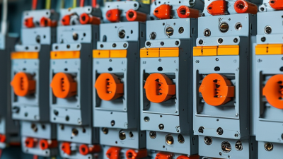
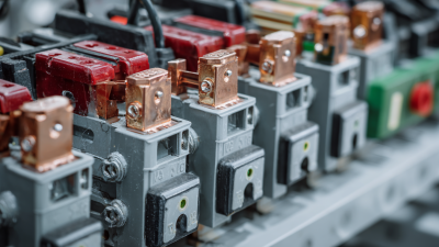
An electric circuit breaker is an automatic safety device that interrupts current during abnormal conditions. Its purpose is to protect wiring, equipment, and people from dangerous electrical faults. Unlike a simple switch, it can respond without manual control. The core components include fixed contacts, moving contacts, a trip mechanism, and an arc-control chamber. Many breakers also contain thermal and magnetic trip elements.

The thermal element reacts to prolonged overloads. A bimetal strip bends as heat increases, releasing the trip mechanism. The magnetic element responds faster to a sudden short circuit. Its coil creates a strong magnetic force and opens the contacts almost immediately.

When the contacts separate, an electrical arc can form. The arc chamber divides and cools it, reducing damage inside the enclosure. That small detail matters.

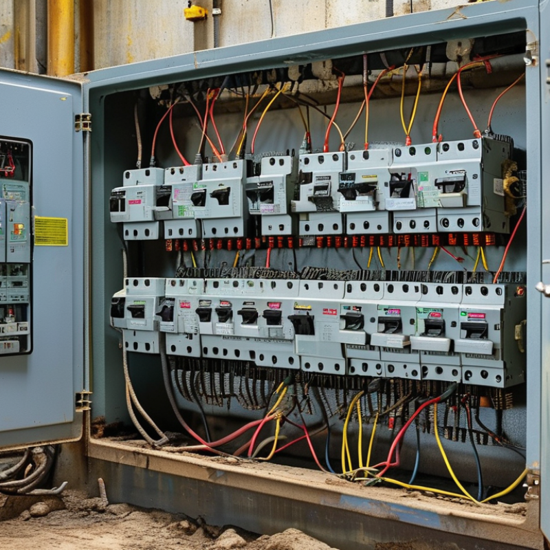
In practical inspections, a breaker may look normal while the connected circuit has loose terminals, moisture, or damaged insulation. A correct rating must match the conductor size and expected load. Oversizing a breaker can leave wiring inadequately protected. Resetting a tripped breaker repeatedly is not a repair. It may hide a continuing fault. Qualified electricians verify the circuit with appropriate test instruments and follow current electrical codes. Testing procedures vary by system, so technical judgment remains important. Real installations are rarely as tidy as diagrams suggest.

How a Breaker Interrupts Current in Milliseconds During a Fault

An electric circuit breaker is an automatic switch that protects wiring from dangerous current. During a fault, its response must be extremely fast. A short circuit can produce a sharp surge within milliseconds. That energy may heat conductors, damage insulation, or create an arc.

Inside a conventional breaker, a magnetic trip mechanism senses the sudden current increase. The magnetic force pulls a small latch, releasing a spring-loaded contact arm. The contacts separate rapidly, often before a person could react. The current does not always stop instantly. An electrical arc can stretch between the opening contacts. Special metal plates divide, cool, and weaken the arc until it is extinguished. The entire interruption may take only a few milliseconds, depending on the fault level and breaker design.

Not every fault creates the same response. A moderate overload may heat a bimetal strip and trip after several seconds. A severe short circuit activates the magnetic mechanism almost immediately. In the field, a breaker that trips repeatedly should not be reset again and again. The cause may be damaged insulation, a failed appliance, or loose wiring. I have found that the visible switch position can be misleading; internal damage is not always obvious. Testing requires suitable instruments and proper training, especially inside energized equipment. Timing also varies with temperature, current, maintenance, and the breaker’s rated capacity.

What Is an Electric Circuit Breaker and How Does It Work? - How a Breaker Interrupts Current in Milliseconds During a Fault

Data Category Dimension Typical Value or Range Technical Description
Circuit Breaker Fundamentals
Definition Primary function Automatic fault-current interruption A circuit breaker is a resettable switching device that opens an electrical circuit when current exceeds a defined limit or another detected fault condition occurs.
Normal operation Current path Closed contacts with low electrical resistance When the circuit is healthy, the contacts remain closed and carry the load current with minimal voltage drop.
Fault protection Common fault types Overload, short circuit, ground fault, and earth leakage The sensing and trip system identifies abnormal current or leakage and releases the operating mechanism to separate the contacts.
Operating state Available positions ON, TRIPPED, and OFF After a trip, the handle or mechanism may rest in a tripped position. The circuit must be reset only after the fault has been identified and corrected.
How the Breaker Interrupts Current
1. Fault begins Electrical event Current rises above the permitted level A short circuit can produce a very rapid current increase, while an overload may develop more gradually as connected loads exceed the circuit rating.
2. Fault detection Sensing method Thermal, magnetic, electronic, or residual-current sensing The sensing element detects excessive current, a rapid current rise, or an imbalance between line and return conductors.
3. Trip release Mechanical action Latch releases the spring-loaded mechanism The trip unit unlatches the mechanism. Stored spring energy then drives the contacts apart without relying on the operator to move the handle.
4. Contact separation Arc formation An electrical arc may form between separating contacts Because current attempts to continue flowing through the ionized gap, an arc can appear briefly as the contacts open.
5. Arc extinction Arc-control method Arc chute, air gap, vacuum, or insulating gas The breaker lengthens, cools, divides, or removes the conductive arc path so that the current can no longer sustain it.
6. Circuit isolation Final condition Open contacts and no intentional load-current path Once the arc is extinguished, the downstream circuit is electrically separated from the source, limiting equipment damage and reducing fire risk.
Typical Breaker Technologies
Thermal-magnetic breaker Trip principles Thermal bimetal for overload; magnetic solenoid for short circuit The thermal element responds more slowly to sustained overcurrent, while the magnetic element provides rapid operation during high-current faults.
Electronic-trip breaker Trip principles Current transformers or sensors with electronic processing Electronic sensing can provide adjustable long-time, short-time, instantaneous, and ground-fault protection settings.
Residual-current breaker Trip principle Difference between outgoing and returning current The device trips when current imbalance indicates that part of the current may be flowing through an unintended path, including a person or protective conductor.
Vacuum circuit breaker Arc-interruption medium High-vacuum contact chamber Vacuum breakers are commonly used in medium-voltage systems because the vacuum allows rapid dielectric recovery and effective arc interruption.
Air circuit breaker Arc-interruption medium Atmospheric air with arc-control structures Air breakers use contact spacing and arc chutes to cool, divide, and extinguish the arc, particularly in low-voltage and higher-current installations.
Representative Operating Characteristics
Low-voltage branch protection Common system voltage Approximately 120 to 480 V AC Used for residential, commercial, and light industrial distribution. The exact voltage depends on the electrical system and installation standards.
Medium-voltage protection Common system voltage Above 1 kV and commonly up to about 38 kV Medium-voltage breakers generally use vacuum or other specialized interruption technologies and require coordinated protection settings.
Continuous current rating Allowable load current From a few amperes to several thousand amperes The rating indicates the current the breaker can carry continuously under specified conditions. It is not the same as the short-circuit interrupting rating.
Interrupting rating Maximum fault current Common low-voltage values range from about 5 kA to 100 kA The interrupting rating is the maximum fault current the breaker is designed to safely interrupt at a specified voltage and under defined test conditions.
Short-circuit response Trip and interruption interval Typically a few milliseconds to several tens of milliseconds The exact time depends on breaker design, fault magnitude, system frequency, contact travel, and the time required to extinguish the arc.
Power-frequency cycles Timing reference One 50 Hz cycle = 20 ms; one 60 Hz cycle ≈ 16.7 ms Breaker operating speed is often expressed in cycles. A three-cycle interruption takes approximately 60 ms at 50 Hz or 50 ms at 60 Hz.
Important Selection and Safety Data
Voltage rating Maximum system voltage Must be equal to or greater than the circuit voltage A breaker must be suitable for the system voltage so that its insulation and arc-interruption capability remain adequate when the contacts open.
Current rating Continuous current Selected to protect the conductors and connected equipment The breaker rating should be coordinated with conductor ampacity, installation conditions, load characteristics, and applicable electrical codes.
Trip curve Time-current behavior Defines how quickly the breaker trips at different overcurrent levels A time-current curve shows the relationship between fault magnitude and clearing time, helping engineers coordinate upstream and downstream protective devices.
Reset capability Post-trip operation Usually resettable after the fault is cleared Most circuit breakers can be reset, but repeated tripping may indicate damaged equipment, wiring problems, or an incorrectly sized protective device.
Maintenance requirement Inspection focus Connections, insulation, mechanism, trip function, and contamination Periodic inspection helps verify that terminals remain tight, insulation is sound, moving parts operate correctly, and protective settings remain appropriate.

Note: Actual trip and clearing times vary by breaker construction, current magnitude, voltage, frequency, temperature, and manufacturer test conditions. Always use the applicable product documentation and electrical safety standards for design or installation decisions.

Breaker Ratings: Voltage, Current, Frequency, and 6 kA Interrupting Capacity

An electric circuit breaker is an automatic safety switch. It opens a circuit when current becomes dangerous. Inside, a thermal element responds to prolonged overloads, while a magnetic mechanism reacts to short circuits. The contacts separate quickly, creating an arc that must be controlled safely. In field inspections, a breaker may look normal while its rating is unsuitable. That hidden mismatch can damage wiring.

Voltage rating must meet or exceed the system voltage. A 230 V breaker is not automatically suitable for every 230 V installation.

Current rating protects conductors, not just appliances. Selection depends on wire size, installation method, ambient temperature, and expected load.

Frequency also matters because heating and interruption behavior can differ at 50 and 60 Hz.

The interrupting capacity indicates the maximum fault current the breaker can safely stop under specified conditions. A 6 kA rating means up to 6,000 amperes, not normal operating current.

A quick label check feels sufficient, but it is not.

Tips:

Read the panel label and installation diagram carefully. Check the prospective short-circuit current before choosing a replacement. Confirm voltage, current, frequency, and interrupting capacity together. Never increase the current rating to stop nuisance tripping. That may hide an overloaded circuit. When conditions are unclear, ask a qualified electrician to test the installation with suitable equipment. Guesswork has no place here.

Common Breaker Types: MCBs, MCCBs, RCDs, and 30 mA Shock Protection

An electric circuit breaker interrupts current when a circuit becomes unsafe. MCBs use thermal and magnetic mechanisms. They respond to overloads and short circuits. IEC 60898-1 covers many low-voltage MCB applications, commonly below 125 amperes. Their compact size suits lighting circuits, sockets, and small equipment.

MCCBs handle higher currents and offer adjustable trip settings. IEC 60947-2 covers these devices in industrial distribution systems.

RCDs work differently. They compare outgoing and returning current, then disconnect when leakage appears. They do not replace overcurrent protection.

IEC 60364-4-41 identifies 30 mA RCDs as additional protection for many socket-outlet circuits. At five times rated residual current, common devices can trip within 40 milliseconds under applicable testing requirements.

That speed matters near a wet floor.

NFPA’s Fire Loss in the United States During 2023 report estimated 1,388,500 fires nationwide. Electrical faults are only one contributor, but poor connections can turn a warm terminal into a serious hazard. On inspection, a correct rating, tight termination, and clear circuit labeling matter as much as the breaker itself.

A 30 mA device is not a magic shield. It may not prevent every shock, especially through simultaneous contact with live and neutral conductors. Monthly test-button checks are sensible, although they do not replace professional verification with calibrated instruments. The uncomfortable truth is simple: protection can be installed correctly and still be neglected later.

Testing and Standards: IEC 60898-1, UL 489, and 50/60 Hz Systems

An electric circuit breaker interrupts current when overloads or short circuits create unsafe conditions. Testing proves whether it opens quickly, repeatedly, and safely. IEC 60898-1 covers household and similar circuit breakers for alternating-current systems. Its scope includes devices up to 440 V, 125 A, and 25 kA short-circuit capacity. These limits matter. A 50 Hz installation may require different verification from a 60 Hz installation, especially when magnetic trip behavior changes.

UL 489 evaluates circuit breakers for low-voltage power circuits, including construction, temperature rise, endurance, and short-circuit performance. Test laboratories apply controlled fault currents, then inspect contacts, terminals, insulation, and enclosure damage. The result is more than a trip-time number. It is evidence that the device can interrupt energy without creating unacceptable hazards. The IEA’s Electricity 2024 report recorded global electricity-demand growth of about 2.2% in 2023 and forecast average annual growth of 3.4% through 2026. Expanding loads make verification increasingly important.

Frequency is not a decorative specification. It affects impedance, magnetic forces, and thermal behavior. Engineers should test at the declared 50 or 60 Hz rating, not assume interchangeability. Field conditions remain messier than test benches. Loose terminals, heat, and repeated switching can change performance. A standard-compliant result is strong evidence, but installation quality still deserves skeptical review. Test records should identify voltage, frequency, current, temperature, trip time, and fault level clearly. Without those details, a certificate may look precise while hiding an incomplete comparison.

Blogs