
How to Choose a Digital Signal Isolator?

Choosing a Digital Signal Isolator is not a part-number exercise. It is a safety and signal-integrity decision. The right device must match the interface, isolation requirement, operating environment, and expected lifetime. A useful design reminder, offered here as an editorial paraphrase rather than a verified verbatim quotation, is: “Choose isolation around the system’s real stresses, not just its headline data rate.” This reflects the practical approach associated with isolation engineer Alan Walsh; verify any direct quotation against an original source before publication.

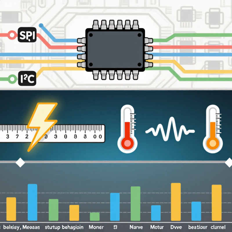
Start with the signals. SPI, I²C, UART, and isolated gate-drive circuits place different demands on channel count, direction, timing, and logic levels. A 25 Mbps rating may look generous, yet it does not guarantee clean edges across a long board trace or heavy capacitive load. Check propagation delay, channel-to-channel matching, pulse-width distortion, and startup behavior. Small details matter.

Then examine the isolation barrier. Compare working voltage, surge capability, creepage and clearance needs, and the relevant safety certifications for your end product. These ratings are not interchangeable. A compact package can save board space, but may complicate routing around the barrier. Look closely at the layout.

Also consider common-mode transient immunity, supply range, power consumption, and temperature limits. In a motor drive, fast switching edges can disturb communication even when the data rate is modest. Test the isolator in the actual circuit, with realistic loads and switching conditions. That step is often overlooked.

This outline will help readers compare device architectures, decode datasheet specifications, and avoid common selection errors. No choice is perfect. The final decision should balance electrical performance, isolation requirements, layout constraints, availability, and evidence from testing.
How to Choose a Digital Signal Isolator?

Define the Signal Type and Application Requirements

Before selecting a digital signal isolator, identify what the signal carries. A slow status bit has different needs from a fast clock or encoder pulse. Check the logic standard, input voltage, channel count, and maximum data rate. Count edges, too. A narrow pulse can disappear if the isolator’s pulse-width limits are overlooked.

Timing matters. Compare propagation delay and channel-to-channel skew with the system’s timing budget. For a motor-control board, for example, delayed or uneven gate-control signals can affect switching behavior. Check common-mode transient immunity when noisy voltage changes may occur across the isolation barrier. Review the isolation rating against the equipment’s actual working voltage and required safety design; a headline test value alone is not enough.

Then consider the installation. Board space, operating temperature, supply voltage, and expected noise all shape the choice. Some devices offer default-high or default-low outputs during startup or input loss. Verify that behavior against the receiving circuit. Read the datasheet’s test conditions, not just its maximum figures. Bench testing with the real cable and load is useful. I’ve seen timing look fine on paper, then shift with board layout. That detail is easy to miss. Decide which failure mode the system can tolerate before finalizing the part.

Determine Isolation Voltage and Safety Needs

When choosing a digital signal isolator, distinguish its working voltage from its short-duration withstand rating. They describe different conditions. A 5 kVrms test rating does not mean the device can safely withstand 5 kVrms continuously. Check the datasheet’s maximum working voltage, transient isolation rating, and test duration. IEC 60747-17:2020 provides requirements for magnetic and capacitive digital isolators, while IEC 60664-1:2020 covers insulation coordination. Use these standards to match the component’s ratings to the equipment’s actual voltage and overvoltage conditions. A quick glance at one headline number can miss the important limits.

Then check how the isolator will be installed. Creepage is the path along the insulating surface; clearance is the shortest path through air. Board contamination, humidity, and narrow spacing can undermine an otherwise suitable rating. Altitude matters too: IEC 60664-1:2020 lists a clearance correction factor of 1.00 at 2,000 m and 1.14 at 3,000 m. That difference can affect spacing decisions in equipment used at elevation. Review the applicable safety standard, pollution degree, and required surge category for the end product. Not the whole story. I still find that test voltage gets more attention than continuous working voltage, though the latter often better reflects the real operating risk.

Compare Data Rate, Timing, and Channel Specifications

How to Choose a Digital Signal Isolator? Compare Data Rate, Timing, and Channel Specifications

Start with the data rate your system actually needs, then leave room for bursts and future changes. A sensor link running at 2 Mbps may appear simple, but cable capacitance and receiver loading can affect signal quality. Check the isolator’s maximum rate under conditions similar to your design, not just its headline rating. The fastest option is not always the best fit.

Timing details matter. Compare propagation delay, pulse-width distortion, and channel-to-channel skew with your controller’s timing budget. For example, skew between clock and data channels can reduce setup time in a tightly timed interface. Check timing across the expected supply voltage and temperature range. A quick bench test with the real cable and load can reveal problems that a datasheet comparison misses. Small details matter. I would not treat one successful test as proof; test the slowest and fastest expected conditions too.

Tips: Count channels and check whether each supports input, output, or both. Match the package and isolation rating to the board layout. Keep a little margin.

Assess Power, Package, and Environmental Compatibility

How to Choose a Digital Signal Isolator?
Assess Power, Package, and Environmental Compatibility

A digital signal isolator should fit the whole circuit, not just the logic signal. Check its supply range, channel count, data rate, and power budget against the actual board. A device with separate input- and output-side supplies may simplify some designs, but it can add routing and startup constraints. Estimate current at the expected switching rate, then allow margin for nearby loads and temperature. Small details matter. Verify isolation rating and working voltage separately; they describe different limits, and neither replaces careful system-level design.

Package choice affects more than assembly. Compare pin pitch, footprint, creepage and clearance needs, and available layout space around the barrier. A compact package may save board area, yet leave less room for routing or spacing. Check the recommended land pattern, and inspect the assembled board for contamination paths near the isolation gap. Check the gap. Environmental conditions deserve equal attention: confirm operating temperature, humidity, vibration, and altitude against the real installation, not just a typical lab bench. If the enclosure traps heat, measure local temperature near the device during demanding operation. Datasheet limits help, but real margins can be less generous than expected. Revisit assumptions before finalizing the layout.

How to Choose a Digital Signal Isolator? - Assess Power, Package, and Environmental Compatibility
Selection Dimension What to Check Typical Data or Considerations How to Choose
Channel Count and Direction Number of isolated channels and signal direction on each channel. Common configurations include 1 to 6 channels, with options for all-forward, all-reverse, or mixed-direction signals. Match the channel count and direction to the interface signals. Allow spare channels only when the added cost and board area are justified.
Data Rate and Timing Maximum data rate, propagation delay, pulse-width distortion, and channel-to-channel skew. Available data rates vary by device; many families offer options from a few megabits per second to tens or over 100 megabits per second. Choose a data-rate rating above the required signal rate, then verify timing limits at the intended supply voltage and temperature.
Power Requirements Supply voltage, current, logic-level compatibility, and whether isolated-side power is required. Digital isolators commonly use separate supplies on each side. Some products integrate isolated power, while others require an external isolated DC/DC converter. Check both sides’ supply ranges and budget total system power, including any external converter. Integrated power can simplify the design but may have different output-current or noise limits.
Isolation Rating Withstand voltage, working voltage, surge capability, and applicable safety approvals. Withstand ratings are test values and are not interchangeable with continuous working-voltage ratings. Ratings and test conditions differ among devices and standards. Use the working voltage and safety requirements of the end application to select a device. Confirm the relevant test duration, standard, and approval documentation.
Common-Mode Transient Immunity Common-mode transient immunity (CMTI), usually specified in kV/µs. Many devices specify CMTI in the tens of kV/µs or higher; the guaranteed value depends on the device and test conditions. Select a rating with margin over expected switching transients, especially near fast-switching power stages. Review the datasheet test setup and logic-state conditions.
Package and Board Layout Package dimensions, pin count, creepage and clearance, and PCB footprint. Common package styles include narrow-body and wide-body surface-mount packages. Package dimensions and isolation spacing vary by construction and rating. Confirm the footprint and required board-level creepage and clearance. Do not assume that a package name alone guarantees compliance with a specific system insulation requirement.
Operating Environment Operating temperature range, humidity exposure, vibration, and contamination conditions. Commercial-temperature parts are often rated around 0°C to 70°C; industrial options commonly extend to about −40°C to 85°C or higher. Exact limits are device-specific. Choose a temperature grade that covers the measured ambient and board temperatures, with margin. Check qualification and environmental limits for the application.
Fail-Safe Output Behavior Output state when the input is floating, unpowered, or across a power-up or power-down transition. Some devices default to a logic-high output and others to logic-low; behavior depends on the device and pin configuration. Match the default state to the system’s safe condition and verify behavior during startup, shutdown, and loss of either-side power.
EMC and Signal Integrity Input thresholds, output drive, edge rate, decoupling, and sensitivity to board-level coupling. Fast edges and long traces can increase ringing or emissions. Local bypass capacitors are generally recommended near each supply pin pair. Follow the datasheet layout guidance, keep bypass paths short, and evaluate signal integrity and emissions in the final PCB layout.
Qualification and Compliance Safety certifications, component qualification, and documentation needed for the end product. Approvals and qualification status vary by device and may apply only under specified conditions. Verify certificates, ratings, and qualification records against the requirements of the target market and end application.
Typical ranges are illustrative selection guidance, not guaranteed specifications. Confirm all electrical, thermal, isolation, and compliance limits in the selected device’s datasheet.

Verify Compliance, Reliability, and System-Level Fit

A digital signal isolator must satisfy the insulation rules for its actual working environment, not just a headline isolation-voltage rating. Check its certification against IEC 60747-17 and applicable UL 1577 requirements, then verify creepage, clearance, pollution degree, and altitude in the end equipment. Read the test conditions carefully. A brief withstand test does not establish long-term operating life.

Reliability depends on more than isolation barriers. Compare the specified common-mode transient immunity, operating temperature, supply range, propagation delay, and expected lifetime with measured system conditions. For example, a noisy motor drive can produce fast voltage edges that challenge an isolator even when its steady-state voltage seems acceptable. Check failure behavior, too: Will a lost supply create a safe output state? Uptime Institute’s 2024 Annual Outage Analysis reported that 54% of respondents’ most recent significant outages cost more than $100,000. That figure is not isolator-specific, but it shows why component choices deserve system-level scrutiny.

Fit the device to the complete signal path. Confirm channel count, logic thresholds, timing margins, PCB spacing, and compatibility with adjacent drivers and receivers. Review test data across temperature and supply extremes, rather than relying on a typical value. A datasheet can look reassuring. Bench testing may still reveal surprises. One imperfect but useful step is to prototype the isolator on the intended board, with representative switching noise and load conditions, before finalizing the design.

How to Choose a Digital Signal Isolator

Verify compliance, reliability, and system-level fit. Common digital logic supply rails include 1.8 V, 2.5 V, 3.3 V, and 5.0 V. Match the isolator’s input and output thresholds to the actual supplies on each side; nominal rail voltage alone does not confirm compatibility.

Selection checks: Confirm the applicable safety approvals and working voltage, creepage and clearance, CMTI, propagation delay, channel count, and fail-safe behavior in the device datasheet. The rails shown are common nominal values, not a compatibility guarantee.

Blogs