
How to Choose a High Torque Brushless DC Motor

Choosing a High Torque Brushless Dc Motor begins with the load, not the largest number on a product page. A conveyor lifting a steady carton needs different performance from a robotic joint that accelerates, stops, and reverses every few seconds. Peak torque matters, but so do continuous torque, speed range, voltage, and heat. Small details count. A warm motor casing after a short test is a warning, not a verdict.

Ned Mohan, an electrical engineering professor and author of Electric Machines and Drives, has shaped practical understanding of electric drives. A useful paraphrase of his engineering approach is: “Match the motor and drive to the real load, not a headline specification.” This is a paraphrase, not a verbatim quotation. It captures a point buyers can miss: the controller, power supply, and motor must work as a system. A motor may advertise impressive torque yet fall short under sustained load or at the required speed.

This guide outlines how to compare torque curves, duty cycles, motor dimensions, feedback options, and cooling needs. It also explains what to ask suppliers, from test conditions to overload limits. Check the fine print. A figure without its test conditions tells only part of the story. And judgment still matters: calculations narrow the choices, but a prototype can reveal vibration, noise, or heat that a spreadsheet cannot.
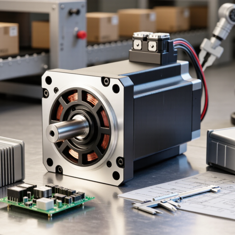
How to Choose a High Torque Brushless DC Motor

Define the Torque and Speed Requirements

Start with the load, not the motor catalog. Record the torque needed at the shaft and the speed required during normal operation. Include startup, acceleration, and brief impact conditions. A conveyor carrying a full bin may need far more torque at startup than while moving steadily. Measure both.

Separate continuous torque from peak torque. Continuous torque must fit the motor’s thermal rating over the full duty cycle; peak torque is usually available only briefly. Note how long each peak lasts and how often it repeats. Estimate speed at the actual working point, not just the motor’s no-load speed. Friction, changing loads, and a gearbox can shift that point. Heat matters.

Check acceleration requirements, too. A heavy drum may demand extra torque even when its final speed is modest, because the motor must overcome rotational inertia. If the load varies, calculate the worst realistic case and leave a sensible margin. An estimate can look convincing yet miss how a warm motor slows during repeated cycles. That uncertainty is worth taking seriously. Test with the real load when possible, recording shaft speed, current, and case temperature over several cycles. Revise the requirements if the data disagrees.

Calculate the Motor’s Required Power and Operating Range

Start with the load, not the motor catalog. Record the torque needed at the shaft, the target speed, and how quickly the load must accelerate. Mechanical power is torque multiplied by angular speed: P = T × RPM × 0.1047, with power in watts and torque in newton-metres. For example, 1.5 N·m at 600 rpm requires about 94 W at the shaft. That figure does not include losses.

Allow for friction, transmission losses, and acceleration. A heavy rotating assembly can demand much more torque during startup than it does once it is moving. Estimate those demands from measurements where possible; guesses about friction are often too optimistic. An estimate is still an estimate.

Then check the motor’s torque-speed curve against the full operating range. Confirm it can provide the required continuous torque at the intended speed, not just a brief peak. Peak torque may be available only for seconds before heat becomes a concern. Consider supply voltage, controller limits, cooling, and duty cycle, especially in a compact enclosure with little airflow. If a gearbox is used, include its ratio and efficiency in the calculations.

Leave a practical margin, but avoid choosing a motor so large that it adds unnecessary cost, weight, or control difficulty. Test the candidate under a representative load. Measure speed, current, and case temperature after it has run long enough to warm up. A short bench test can miss the thermal limit.

Compare Electrical Ratings and Torque Characteristics

Compare rated voltage and current with the real DC bus and controller limits, not just headline wattage. Continuous torque matters when a load must run for minutes or hours; peak torque serves brief acceleration. Check the torque-speed curve at your intended voltage. A motor can produce strong low-speed torque, then lose it as back-EMF rises. Cooling and mounting space matter, too. Heat is the quiet limit. It is tempting to trust a peak figure; question it unless its duration and thermal conditions are stated.

For a quick check, estimate torque using T (N·m) = 9550 × power (kW) ÷ speed (rpm), then compare it with the required shaft load. Also check torque constant: for a given motor, torque generally rises with current, until electrical or thermal limits intervene. The U.S. Department of Energy’s 2014 Improving Motor and Drive System Performance sourcebook reports that motor-driven systems use about 70% of U.S. industrial electricity. That broad figure is not a BLDC motor rating, but it underlines why matching motor, drive, and duty cycle matters. Leave margin for warm ambient conditions and repeated starts. A little conservative sizing can prevent trouble; too much can waste space and energy.

Evaluate Thermal, Mechanical, and Environmental Limits

How to Choose a High Torque Brushless DC Motor

Evaluate Thermal, Mechanical, and Environmental Limits

High torque often means high current, and current produces heat in the windings and drive electronics. Check the motor’s continuous torque rating at the actual ambient temperature, not just its peak value. A brief stall test can hide a thermal problem. Real duty cycles are rarely neat. The U.S. Department of Energy’s Improving Motor and Drive System Performance sourcebook reports that motor-driven systems use about 68% of U.S. manufacturing electricity. That makes system-level losses worth checking, not just the motor’s headline efficiency.

Compare winding temperature limits with the motor’s cooling method and expected operating cycle. IEC 60034-1 defines insulation thermal classes, including Class F at 155°C and Class H at 180°C; these are insulation-system limits, not recommended everyday winding temperatures. Leave margin for hot enclosures, slow operation, and repeated acceleration. A datasheet can look tidy while real heat builds inside a cramped machine.

Mechanical limits matter just as much. Verify shaft load, bearing life, maximum speed, and coupling alignment against the machine’s actual forces. For wet or dusty settings, use IEC 60529 ingress ratings carefully: IP67 indicates dust-tight protection and specified temporary immersion conditions, not suitability for every washdown or submerged application. Check cable entries and seals too. They are easy to overlook. A small mismatch here can become an expensive failure.

How to Choose a High-Torque Brushless DC Motor

Evaluate thermal, mechanical, and environmental limits. This chart shows the calculated mechanical power for a constant reference torque of 1 N·m at different speeds, using P = T × 2π × rpm / 60. It is a physics-based reference, not a specific motor performance curve.

When selecting a motor, compare its torque-speed curve with your load, then check continuous and peak torque against winding temperature, cooling, maximum speed, mounting loads, and the operating environment.

Match the Motor with a Controller and Application Setup

A high-torque brushless DC motor needs a controller that can handle its electrical demands, not just its advertised power. Check the motor’s rated voltage, continuous current, and peak current, then compare them with the controller’s limits. A mismatch can cause overheating, shutdowns, or weak starting torque. Start with the load. A conveyor moving steadily has different needs from a mechanism that starts and stops under heavy load.

Match the controller’s commutation method to the motor’s sensors. Hall sensors can provide reliable low-speed starting, while sensorless control may struggle when a loaded shaft begins from rest. Confirm that the controller supports the required feedback and speed range. Then consider the power supply, wiring, and cooling. Thin cables can lose voltage under high current, and a controller boxed into a warm enclosure may need airflow. Small details matter.

Set current limits carefully. A generous peak setting may help brief acceleration, but repeated surges can heat the windings and controller. Test the complete setup with the real load, not only a free-spinning motor. Measure current and temperature after several starts. Measure it warm. One practical limitation: a short bench test cannot predict every duty cycle. Recheck the settings after installation, especially if the load varies or the motor runs near its torque limit.

Blogs