Choosing the right motor protection in 2026 requires more than comparing prices or enclosure labels. Buyers must understand how motors fail in real operating environments. Heat, stalled shafts, phase imbalance, voltage loss, dust, and repeated starts can damage equipment quietly. A reliable protection plan connects each risk with a suitable device.
This guide introduces the main motor protection types buyers should evaluate. Thermal overload relays remain practical for many standard applications. Electronic overload relays offer more precise adjustment and useful diagnostic data. Circuit breakers and fuses help control short-circuit energy, while ground-fault and phase-monitoring devices address additional electrical hazards. Variable-frequency-drive systems require compatible protection and careful parameter settings.
Look beyond the catalogue.
An experienced installer will check the motor’s full-load current, starting method, duty cycle, ambient temperature, and cable length. These details often matter more than a familiar brand name. In a dusty workshop, for example, heat buildup may reduce the protection margin. In a pump station, dry running or frequent starts may create different concerns.
The best motor protection choice is not always the most advanced one. A simple device can perform well when correctly selected, installed, and tested. However, product data can be confusing, and field conditions are rarely perfect. Buyers should verify ratings against current manufacturer documentation and applicable regional standards. This article compares practical options, explains their strengths and limitations, and highlights questions worth asking before purchase. Some recommendations may need adjustment after a site inspection. That is a useful reminder, not a weakness.
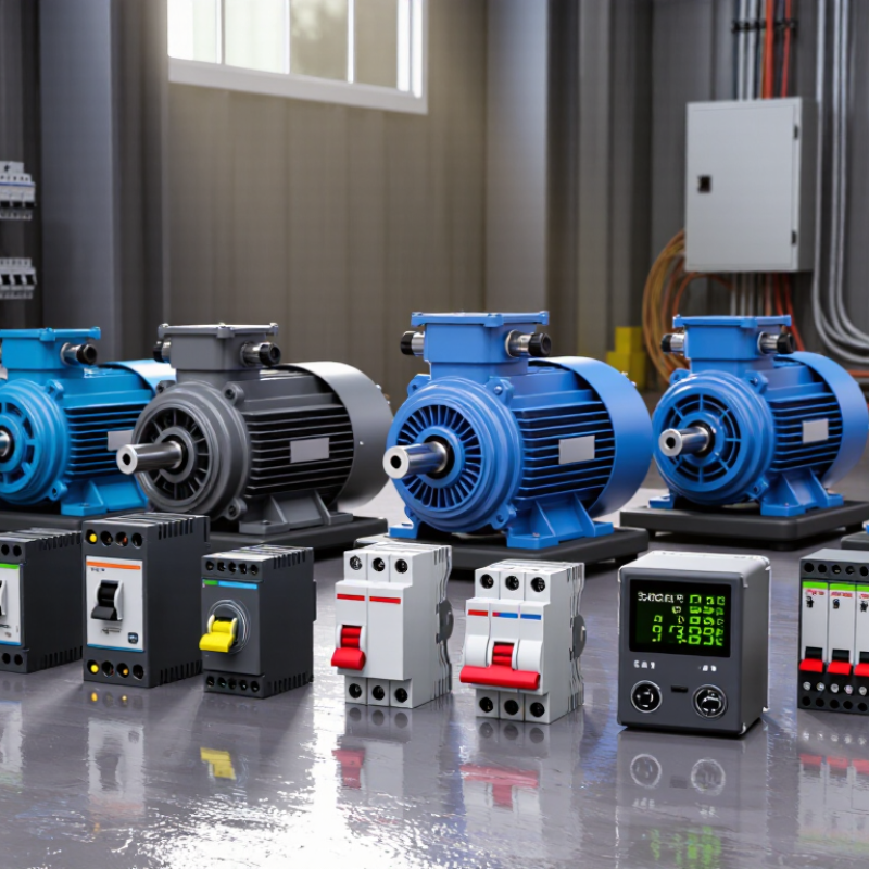
Motor protection is the working safety system around an electric motor. It detects overloads, short circuits, phase loss, voltage imbalance, overheating, and ground faults. Without suitable protection, a motor may stall, burn insulation, damage connected equipment, or stop production unexpectedly. In 2026, buyers also need to consider energy quality and operating data. Modern protection devices can track temperature, current changes, and repeated trip patterns before failure becomes obvious.
Choosing protection starts with the motor’s real environment. A dusty workshop, cold warehouse, or pump room creates different risks. Thermal overload protection helps during sustained heavy loads. Short-circuit protection reacts faster to severe electrical faults. Phase monitoring matters for three-phase motors, especially where unstable supply conditions occur. For critical equipment, communication features can support maintenance teams with clearer records. Yet digital monitoring is not a substitute for correct sizing or inspection. I have seen systems collect impressive data while basic wiring problems remained unnoticed.
Tips: Match protection to the motor’s rated current, starting method, load profile, and installation conditions. Check settings during commissioning, then review them after process changes. Keep inspection records, including trip times and measured temperatures. Do not rely on factory defaults without verification. Ask a qualified electrician to test coordination between protective devices. Small errors in settings can create nuisance trips, or worse, delayed protection.
Motor protection starts with the motor’s real operating conditions. The IEA estimated that electric motor systems consume 43–46% of global electricity. That figure makes protection a reliability issue, not only a maintenance preference.
Thermal overload relays detect sustained overcurrent and protect windings from damaging heat. They do not normally clear short circuits. Fuses and circuit breakers handle high fault currents, while motor circuit protectors coordinate isolation and restart control. Ground-fault protection detects leakage caused by insulation damage or moisture.
Electronic motor protection relays add phase-loss, phase-sequence, under-voltage, over-voltage, and locked-rotor functions. These features matter in pumps, compressors, conveyors, and fans with frequent starts. The U.S. Department of Energy’s Motor Systems Market Assessment reported that motor-driven equipment represented about 68% of industrial electricity use in the United States. Small efficiency losses can therefore become expensive operating losses.
Temperature sensors embedded in windings offer direct thermal feedback, especially for variable-speed or heavily loaded motors. Buyers should check trip classes, fault response time, ambient temperature, and coordination with upstream devices.
A larger device is not automatically safer. Poor settings can delay a trip or cause nuisance shutdowns. That part is often underestimated.
Protection must match the motor, cable, starter, enclosure, and actual load profile. One unresolved question remains: many installations still select devices from nameplate current alone, despite changing duty cycles and harsher environments.
Matching motor protection to the application matters more than choosing the most expensive device. The IEA’s Energy Efficiency 2023 report estimates that electric motor systems use nearly half of global electricity. Small protection errors can therefore create large energy and maintenance losses. In a dusty conveyor area, combine short-circuit protection with adjustable overload protection and phase-loss monitoring. Overload relays protect against sustained current increases. Circuit breakers respond faster to severe faults. They are not interchangeable.
For pumps, dry-running and frequent starting deserve attention. Thermal sensors can detect winding heat before insulation damage becomes visible. IEC 60034-11 provides guidance for thermal protection, while IEC 60947-4-1 covers low-voltage motor starters and overload relays. A compressor with repeated starts may need a higher starting-current allowance, but that setting must still protect the motor cable and winding. Variable-speed drives also change the decision. Their electronic protection may identify overloads, yet upstream short-circuit and ground-fault protection remain necessary. The U.S. Department of Energy’s Motor Systems Market Assessment highlights the large energy impact of industrial motor systems, making nuisance trips costly. Field experience suggests that protection settings are often copied from older equipment. That is risky. Ambient temperature, cable length, duty cycle, and actual starting current should be measured. Sometimes the “right” protection is still wrong after installation. Logging trips for several weeks can reveal whether the problem is overload, poor ventilation, phase imbalance, or an undersized power supply.
Selecting motor protection in 2026 starts with the motor, not the product catalogue. Buyers should record voltage, full-load current, starting method, duty cycle, and ambient temperature. For a small, lightly loaded motor, thermal overload protection may be adequate. Larger or frequently started motors often need electronic protection with adjustable trip settings. Short-circuit protection remains separate from overload protection, so one device rarely covers every risk.
Application conditions matter just as much. Dust, moisture, heat, vibration, and frequent starts can change protection requirements. In field inspections, I have seen correctly rated devices fail because panels were poorly ventilated. Check enclosure ratings, wiring space, reset access, and compatibility with control circuits. Phase loss, locked-rotor, ground-fault, and underload detection may also deserve attention. Select only functions that match the operating risk. Extra features can create confusion.
Maintenance teams should compare trip accuracy, alarm visibility, test procedures, and replacement availability. Clear fault codes reduce troubleshooting time near a noisy machine. Communication features help in larger facilities, but they should not replace local inspection. Ask for test records, coordination data, and independent compliance evidence. A low purchase price can hide calibration limits or difficult servicing. I still find this trade-off underestimated. The first setting is rarely perfect; real operating data may require a careful adjustment after installation.
| Protection Type | Primary Function | Main Faults or Conditions Covered | Typical Adjustability | Starting-Current Suitability | Coordination Role | Key Advantages | Main Limitations | Best-Fit Applications | Buyer Selection Checks |
|---|---|---|---|---|---|---|---|---|---|
| Thermal Overload Relay | Protects against sustained motor overcurrent caused by overload or phase loss. | Long-duration overload; some models respond to phase failure or current imbalance. | Usually adjustable within a defined motor-current range; trip class is commonly selectable on applicable models. | Generally suitable when the trip setting and trip class match the motor starting profile. | Normally used with a short-circuit protective device and a contactor as part of a motor starter. | Simple operation, economical installation, and widely understood maintenance requirements. | Does not independently provide full short-circuit protection; thermal response varies with ambient temperature and operating conditions. | General-purpose fixed-speed motors, pumps, fans, compressors, and conveyors. | Verify motor full-load current, trip class, ambient compensation, reset mode, phase-loss response, and compatibility with the contactor. |
| Magnetic-Hydraulic or Thermal-Magnetic Motor Circuit Protector | Provides switching and short-circuit protection, with overload protection available depending on the device configuration. | Short circuits; overload protection on motor-protection circuit breaker designs; some devices also detect phase loss or current imbalance. | Current range and instantaneous magnetic threshold may be adjustable on selected designs; thermal settings vary by construction. | Suitable when instantaneous tripping is coordinated with the motor inrush current and starter requirements. | Can combine disconnecting, short-circuit protection, and overload protection in a compact motor branch circuit. | Compact assembly, local isolation, and reduced component count compared with separate protective devices. | Incorrect magnetic settings can cause nuisance trips during starting; available settings and interrupting ratings differ by design. | Industrial motor starters, machine tools, packaged equipment, and compact control panels. | Check rated operational current, interrupting rating, motor-starting curve, isolation requirements, enclosure rating, and coordination data. |
| Fuse-Based Motor Protection | Interrupts high fault current rapidly and limits let-through energy. | Short circuits and severe overcurrent; overload protection normally requires a separate relay or protective function. | Protection is selected by fuse type, rating, and time-current characteristic rather than continuous adjustment. | Motor-rated fuse systems can accommodate inrush when correctly selected and coordinated. | Often paired with an overload relay and contactor; a fuse-switch combination can provide isolation and fault interruption. | High fault-current interruption capability, fast clearing, and effective energy limitation. | Requires replacement after operation; incorrect fuse selection can cause nuisance opening or inadequate motor protection. | High available fault-current installations, industrial distribution, and applications requiring strong current limitation. | Confirm fuse class, motor-starting characteristic, rated voltage, interrupting rating, coordination type, spare-fuse strategy, and touch protection. |
| Electronic Motor Protection Relay | Monitors electrical and operating conditions and trips or alarms before motor damage occurs. | Overload, phase loss, phase sequence, current imbalance, locked rotor, undercurrent, ground fault, and underload functions may be available. | Typically offers precise current settings, time delays, trip classes, alarm thresholds, and reset logic. | Well suited to demanding starts when the relay provides selectable trip classes and locked-rotor protection. | Used with a contactor or circuit breaker; it does not replace the required branch-circuit short-circuit protective device. | Accurate measurement, diagnostics, event records, communication options, and broader motor-condition coverage. | Higher cost, configuration complexity, and dependence on auxiliary power or control wiring in some installations. | Critical pumps, compressors, production machinery, high-utilization motors, and predictive-maintenance programs. | Review measurement accuracy, sensor compatibility, communication protocol, event logging, cybersecurity requirements, and maintenance skills. |
| Motor Protection Circuit Breaker | Combines manual motor isolation with adjustable overload and instantaneous short-circuit protection in one device. | Overload, short circuit, and commonly phase-loss-related conditions, depending on the design. | Overload current is commonly adjustable; magnetic or instantaneous protection may be fixed or adjustable. | Suitable for direct-on-line starting when the device is selected for the motor inrush current. | Can serve as the protective disconnect ahead of a contactor, subject to the applicable coordination requirements. | Compact, resettable, locally isolatable, and convenient for machine-level motor protection. | Limited adjustment range on some models; may require an additional contactor, auxiliary contacts, or undervoltage release. | Small and medium fixed-speed motors, machine builders, conveyors, fans, and modular panels. | Check motor full-load current range, interrupting capacity, short-circuit coordination, enclosure integration, and required auxiliary functions. |
| Soft Starter with Motor Protection Functions | Controls voltage during starting and stopping while providing selected motor-monitoring and protection functions. | Overload, phase loss, current imbalance, excessive starting time, and thermal stress may be monitored; short-circuit protection remains separate. | Starting ramp, current limit, stop profile, overload class, and alarm thresholds are commonly configurable. | Designed to reduce mechanical shock and limit starting current compared with direct-on-line starting. | Requires upstream short-circuit protection and suitable bypass, isolation, and control arrangements. | Smooth acceleration, reduced voltage dip, lower mechanical stress, and controlled stopping. | Does not provide continuous speed control; generates heat and may require bypass or thermal management. | Pumps, fans, compressors, conveyors, and high-inertia loads that need controlled starting. | Evaluate motor starting torque, load inertia, starts per hour, bypass requirements, semiconductor short-circuit coordination, and cooling. |
| Variable-Frequency Drive with Integrated Protection | Controls motor speed and torque while monitoring electrical, thermal, and drive-related operating limits. | Overcurrent, overload, stall, overvoltage, undervoltage, phase loss, motor overtemperature input, and drive thermal conditions may be covered. | Motor data, current limits, acceleration, deceleration, thermal model, fault thresholds, and control parameters are configurable. | Provides controlled acceleration and can limit current, but motor compatibility and low-speed cooling must be assessed. | Needs input-side short-circuit protection and may require output filtering, braking protection, or additional motor-side safeguards. | Variable-speed operation, energy control in suitable loads, process regulation, and programmable diagnostics. | More complex installation; switching waveforms can increase insulation stress, bearing currents, electromagnetic interference, and motor heating. | Pumps, fans, conveyors, extruders, HVAC systems, and processes requiring speed or torque control. | Confirm motor insulation suitability, cable length, cooling at low speed, EMC measures, braking duty, overload capability, and parameter backup. |
2026 Top Motor Protection Types Buyers Need?
Installation, Testing, and Maintenance Requirements for Safe Operation
Safe motor protection depends on more than selecting overload, short-circuit, or ground-fault devices. Installation quality often decides whether protection works during a real fault. For 2026 projects, buyers should match each device with motor current, starting method, enclosure rating, and site temperature. A qualified electrician should verify conductor sizing, tightening torque, phase sequence, and protective-device settings. Loose terminals can heat silently. That detail is easy to miss.
Testing must begin before energizing the motor. Inspect insulation resistance, continuity, grounding, and control interlocks with calibrated instruments. Record readings, instrument identity, ambient temperature, and test date. During commissioning, compare measured current across all phases under normal load. Uneven current may indicate wiring problems, mechanical resistance, or incorrect settings. Do not treat a successful start as proof of complete safety. It only proves the motor started.
Tips: Label every circuit clearly, keep test records near the control panel, and photograph terminal layouts before changes. Test emergency stops and trip functions under controlled conditions. Maintenance teams should inspect terminals, cooling paths, contact wear, and unusual vibration regularly. Dust can block ventilation. Moisture can damage insulation. Replace damaged parts according to equipment instructions and local electrical requirements. Review protection settings after motor, load, or process changes. Maintenance schedules are sometimes too optimistic; actual dust, heat, and cycling should reshape them.
How to use this chart: The intervals represent a practical baseline for industrial low-voltage motor systems. Actual requirements depend on the installation environment, applicable electrical codes, risk assessment, and equipment manufacturer instructions.